|
Please select from
the list below or the links on the right.
Primary and
Secondary Coil Set
Learning
about Transformers and how they work
| Introduction: The primary &
secondary coil with a center core is basically a transformer. A
transformer is an electrical device without any moving components that
consists essentially of two electrical circuits interlinked with a
magnetic field. The function of
the transformer is to transform electric power from low voltage and
large current to high voltage and low current, or the reverse. |
 |
Transformers can be fun, useful
and dangerous. Caution should be used. Some transformers are capable of
producing enough voltage to kill a person.
 |
| The input circuit or winding
of the transformer is called the primary, and the output circuit
the secondary. The primary and secondary coil can be used to
either step up or down (increase or decrease) the voltage or
current. Power is a
measurement that is derived by multiplying the voltage (in
volts) times the current (in amps). |
|
A transformer does not create
power. So if the voltage increases, the current will go down. If the voltage is
decreased, the current will be increased. The power will always stay the same.
Example:
If the voltage is 20 volts and the current is 2 amps, you may use a transformer
to cut the voltage in half, then the current would double. In other words the
voltage would become 10 and the current would become 4 amps.
20 volts x 2 amps = 40 watts
and 10 volts x 4 amps = 40 watts.
As you see a transformer can
change the voltage and current, but the power remains the same.
How
Transformers Work?
When an alternating current flows
through a conductor, an alternating magnetic field is generated around the
conductor. This alternating magnetic field can induce an alternating current in
any conductor or coil that is close to it.
In a transformer, one of the coils
(known as input or primary) receives the electricity and produces a magnetic
field and the other coil (known as output or secondary) absorbs that magnetic
energy and converts it to electrical energy.
These coils are usually wrapped
around the same core. For power transformers this core is most often made of
iron. Other types of transformers may use other material or no core at all.
In order for a transformer to work the incoming current must be fluctuating.
That is turning on and off or higher and lower. Generally this fluctuating
current is provided by AC power. AC stands for alternating current. AC is
constantly alternating from positive to negative.
As AC passes through a coil that
surrounds an iron core, a varying electromagnetic field is created around the
coil and in the core. This electromagnetic field then induces a second current
in the second coil or coils. This is referred to as induced voltage. The first
coil in which the current is supplied is known as the primary coil, and the coil
with induced voltage is known as the secondary coil.
The relation of
secondary voltage to the primary voltage in a transformer equals to the relation
of windings on the secondary coil to the windings of the primary coil.
If the secondary coil has
twice as many turns as the primary then the induced voltage on the secondary
coil
will be twice as high. If the secondary coil has half as many windings as the
primary then the voltage on the secondary coil will be half as much.
Remember, however, that if the
voltage is cut in half the amperage doubles.
Direct current cannot transfer power by means of a transformer because it does
not generate a changing magnetic field. However, DC voltages can be made to
pulsate on and off to induce a changing magnetic field. This acts almost the
same as AC current.
The primary winding receives electrical energy from a power source and couples
this energy to the secondary winding by means of changing magnetic field. The
energy appears as an EMF across the secondary winding, and if a load is
connected to the secondary, the energy is transferred to the load. A transformer
does not generate electrical power, but merely transfers it.
The primary circuit draws the power from the source, the secondary delivers the
power to the load. The power transferred from the primary to the secondary is
determined by the current flowing in the secondary, which in turn, depends on
the power required by the load. In an ideal transformer the power in the primary
circuit equals the power in the secondary circuit. Since power is voltage times
current or:
Vp x Ip = Vs x Is
Primary Voltage x Primary
Current = Secondary Voltage x Secondary Current
| when the primary and secondary voltages are equal, as in
a case of transformer with equal number of turns in primary and secondary, the
primary current will automatically adjust to the same value as the secondary
current so that the primary and secondary powers are equal. |
 |
Transformer uses
Transformers are used by the power companies for a very good reason. Voltage is
stepped up to as high as 70,000 volts before it is transmitted across the power
lines. This is done for two important reason.
-
Low voltage require much
thicker cables resulting a dramatic increase on the cost of wires and
installations.
-
Low voltage electricity is lost through the wires
much easier than higher voltage. This is known as line loss.
After the
electricity reaches its destination it is once again stepped back down.
However, transformers are not only used to step voltage up or down, they are
also used to isolate different parts of an electrical circuit from each other
because they can allow AC current but block DC current.
Transformer
Experiments
As with any electrical device, normal safety precautions against physical
contact with powered circuits should be exercised. Since secondary design
criteria for the Transformer is maximization of efficiency and in use
durability, coil and core components provided exceed construction requirements
for operation at the recommended voltage range. However, as a matter of policy
the following safety condition should be adhered to:
DO NOT OPERATE THE TRANSFORMER IF CALCULATED VOLTAGE AT THE SECONDARY EXCEEDS 24
VRMS.
In order to experiment with the coil you will need some type of AC or a
pulsating DC power source. You also need a voltmeter or multimeter that measures
volts. Hook up the meter to the secondary post. If you do not have an AC power
source you can briefly touch the low side of the transformer with a DC source
and witness a quick flash of reading on a DC voltmeter hooked to the other side.
This will only last for an instant but it will demonstrate how the sudden
fluctuation through the coil will produce voltage in the other coil.
If you will apply a small AC voltage (i.e. 2 volt) to a transformer primary of
30 windings, you should get a reading of 18 volts on the other side if the
transformer�s secondary has 270 windings. That is because there is a 9 to 1
ratio between the number of turns of
wire on each side. Therefore 2v. x 9 = 18 volts. If you reverse the connections
so that the 2 volts is on the high side and took a reading of the other side you
should get a reading in the vicinity of .22 volts. 2 / 9 = .2222. Again about a
1 to 9 ratio.
Try this for several different voltages but please keep your inputs low because
stepping up voltage like this can become very dangerous. Even with pulsating DC
you can get a pretty good shock if too much is applied to the low side.
BASIC
TRANSFORMER EXPERIMENTS
PLEASE NOTE * A VARIABLE POWER SOURCE IS RECOMMENDED FOR
THESE EXPERIMENTS.
YOU MAY USE ANOTHER
TRANSFORMER TO CREATE LOW VOLTAGE AC CURRENT FOR YOUR EXPERIMENTS
1. Insert the steel rod into the plastic tube, and have the students push it
back and forth to see that it moves freely when there is no current applied to
the coil.
2. Apply power to the coil and have the students push the steel rod slightly out
of position. Notice that the magnetic field has induced a magnetic field in the
steel rod which is related to the magnetic field of the coil, and that the rod
is drawn back to a centered position.
3. Attach an ammeter between one of the power leads and the coil. Measure the
current draw when the coil and the steel rod are in equilibrium.
4. With the ammeter still in place, move the steel rod out of the center
position. Is there an increase in the resistance of the coil?
5. Slowly increase the current supplied to the coil. Does the movement of the
steel rod change as the current is increased? What does this say about the
strength of the magnetic field.
(NOTE: When the coil is being held
vertically, as the magnetic field increases in
strength the steel rod should move more freely, to the point where the strength
of the magnetic field will counterbalance the gravitational force acting on the
rod. At this point the rod should "float" in the center of the plastic tube).
INCREASE THE CURRENT SLOWLY, BEING CAREFUL NOT TO EXCEED SAFE LIMITS.
OBSERVE THE COIL CLOSELY FOR SIGNS OF HEATING.
ADVANCED
TRANSFORMER EXPERIMENTS
1. Carefully weigh the steel bar.
2. Adjust the current to the coil to the point where the rod is just "floating".
3. Using the weight of the rod, and the current required to counteract the
Earth's gravitational field, calculate the strength of the gravitational field
(OR use the strength of an unknown magnetic field). This is a difficult
calculation, and is only to be used for advanced studies.
4. Knowing the size of the coil, is it possible to calculate the resistance of
the wire used in the apparatus? (HINT: measure the resistance of the coil, using
an ammeter, both with and without the steel rod in place).
It may be pointed out that the principles involved in this apparatus are the
same as are used for such applications as automotive starters, door bells, and
switches.
The suggestions for the use of this apparatus are designed to show some of the
possible uses. There are many other applications which the individual instructor
may find useful, and which may be adapted to serve the instructional needs of a
particular curriculum. The instructor should feel free to experiment with this
apparatus, ALWAYS REMAINING AWARE OF PROPER SAFETY CONSIDERATIONS.
TRANSFORMER VOLTAGE: The voltage induced in a coil is equal to the sum of the
many voltages induced in each loop that the flux lines cut.
Assuming that all of the magnetic flux lines pass through both windings, then,
in an ideal transformer, the voltage induced in the secondary will depend on the
ratio of the number of turns in the secondary winding to the number of turns in
the primary winding. This exact relationship in an ideal transformer between the
primary and secondary
voltages (V) and their number of turns (N) can be summarized by following
equations:
Vp
Np
Primary Voltage
Primary Windings
---- = ---- OR
-------------------- = --------------------
Vs
Ns
Secondary Voltage
Secondary Windings
also Vp/Np = Vs/Ns or
Vp/Vs = Np/Ns
Therefore, the secondary voltage is equal to:
Vs = Vp (Ns/Np)
For example, if 12 volts is applied to a step-down transformer with 200 turns in
the primary winding and 100 turns in the secondary winding, then to find the
voltage of the secondary circuit:
Vs = Vp (Ns/Np) = 12V (100/200)
Vs = 6 volts
If the same transformer was used in the step up mode with 12 volts applied to
the primary
circuit having 100 turns, then the voltage in the secondary would be:
Vs = Vp (Ns/Np) = 12V (200/100)
Vs = 24 volts
TRANSFORMER CURRENT: A transformer does not generate power - it transfers power
from the primary coil to the secondary coil. If we assume an ideal transformer then the
power in the primary is equal to power in the secondary or,
Vp x Ip = Vs x Is
Ideal transformer is a
transformer that does not loose any power/ energy in the form of heat.
Since turn ratio determines the relationship between primary and secondary
voltages, turn ratio relationship must exist between primary and secondary
current.
From the power equation it is evident that voltages and current are inversely
proportional to each other. For power in the primary to equal to that in the
secondary, as voltages increase in the secondary currents must decrease and vice
versa. If the number of turns in the secondary directly govern voltage increase
or decrease between primary and secondary, turn ratio between the primary and
secondary will inversely govern currents in primary and secondary.
Ip x
Np =
Is x
Ns or
Is/Ip =
Np/Ns
and the respective currents will equal to,
Ip =
Is (Ns/Np) and
Is =
Ip (Np/Ns)
For example: In the step-down mode, if the primary (N=200) circuit voltage is 12
volts and the current is 4 amps and the secondary (N=100) circuit voltage is 6
volts - current in the secondary will equal:
Is = (VpIp) /Vs = Ip (Np/Ns)
Is= (12Vx4A)/6V = 4A (200/100)
Is= 2 x 4A = 4A x (2)
Is= 8A
Current will flow in the secondary circuit only when a load is attached to the
winding. When no current is drawn from the secondary, i.e. the circuit is open,
the resistance to current flow set up by self-induced voltage or counter EMF
(electromotive force) in the primary winding permits practically no current flow
in that circuit. However, when a load (such as a resistor) is attached to the
secondary winding and current is drawn, the counter EMF in the primary is
reduced resulting in increased current flow in that circuit. The primary current
will increase until the self-induced EMF will balance the induced EMF of the
secondary circuit. Thus the self-induced EMF in the primary and hence the
current in that circuit- will be regulated by the current drawn in the secondary
circuit.
When an AC voltage is applied across a resistance, an AC current flows through
the resistance. The magnitude of the current at any instant is directly
proportional to the magnitude of the voltage at that instant, and is inversely
proportional to the value of the resistance. This is the same relationship that
exists between the current, voltage and resistance in DC circuit, and so, in AC
circuit that contains only resistance, the relationship between the current,
voltage and resistance is that of Ohm's Law. I = V/R
Several examples will help illustrate how we can use Ohm's Law to find magnitude
of current flow in transformer circuits.
STEP-DOWN TRANSFORMER
PRIMARY SECONDARY
Secondary current:
Is = Vs/Rs = 6 V/10 = 0.6A
Primary current:
Ip = (Vs / Vp) x Is = (6V/12V) 0.6A = 0.3A
STEP-UP TRANSFORMER
PRIMARY SECONDARY
Secondary current:
Is = Vs / Rs = 24 V / 10 = 2.4 A
Primary current:
Ip = (Vs / Vp) x Is = (24V/12V) 2.4 A = 4.8 A
TRANSFORMER EFFICIENCY: Ideally transformers should operate without loss of
power during operation; that is, they should transfer 100% of the power from the
primary to the secondary circuit. In any practical transformer, the output power
is less than the input power so the efficiency is less than 100%. Actual losses
do occur, principally through ohmic heating of the copper windings, flux
leakage, and core losses due to eddy currents, hysteresis and saturation loss
within the core.
Mathematically, the efficiency of a transformer is equal to the output
(secondary) power divided by the input (primary) power.
OHMIC AND FLUX LOSSES: Transformer windings are
usually made of many turns of copper wire. As with any wire, these windings have
resistance. The longer the effective length of the wire (number of turns) and
the smaller the cross sectional area of the wire, the greater is the resistance.
When the primary and secondary currents flow through the windings, power is
dissipated in the form of heat. These power losses are proportional to the
square of the current and to the resistance. The total ohmic power loss for a
transformer is equal to the sum of the losses in the primary and secondary
coils. Or
Ohmic Power Loss =
Ip2
Rp
+ Is2
Rs
where the Rp and Rs are the resistances of the primary and secondary
windings respectively.
A source of inefficiency in iron-core transformers results from the fact that
not all of the flux lines produced by the primary and secondary windings travel
through the iron core. Any flux lines that leak from the windings into space and
do not link the primary and secondary windings represent wasted energy and thus
transformer power loss.
HYSTERESIS LOSS:
Hysteresis loss in a transformer depends on the core material
used. In an iron-core transformer, the core is magnetized by the magnetic field
created by the current through the windings. The direction in which the core is
magnetized is the same as the direction of the magnetic field that causes the
core to be magnetized. Thus, each time the magnetic field around the windings
expands and collapses, the direction in which the core is magnetized also
changes. When the magnetic field collapses not all of the core material
molecules assume the random orientation of unmagnetized state. As the magnetic
field reverses direction, additional energy is required to orient these
molecules in the direction of the magnetic field. This energy is the hysteresis
loss of the transformer.
EDDY CURRENT LOSSES: The core material is made of a material that enhances the
magnetic field generated when current is flowing through the windings. However,
this material is also a fair conductor of electricity. Thus, the magnetic field
that induces a voltage potential in the core material resulting in current flow
there as well. These induced currents are called eddy currents. They produce
heat and thus use energy that would otherwise be transferred to the secondary
winding.
To reduce eddy currents, the core of a transformer is usually made up of many
thin sheets laminated or insulated with varnish in a direction perpendicular to
that which the eddy currents would tend to flow. The cross section of each
current path is reduced and the resistance to eddy current flow is increased.
When the current in the primary of an iron core transformer increases, the flux
lines generated follow a path through the core to the secondary winding and back
through the core to the primary winding. As the current begins to increase, the
number of flux lines increases rapidly.
The more current rises the greater is the number of flux lines within the core
until the current has risen to the point where additional rise produces
relatively few additional flux lines. At this point the core is said to be
saturated. Any further increase in primary current after core saturation has
been reached results in wasted power, since the magnetic field cannot couple the
additional power to the secondary.
Solid Core: Eddy current flow is appreciable.
Laminated Core: Cross section of currents reduced, resistance increased. Eddy
current losses reduced.
TRANSFORMER CONSTRUCTION: Commercial transformers of the type commonly used in
electrical devices are constructed to keep leakage of magnetic flux to a
minimum. In an iron core transformer, the laminated core segments are bound
together very tightly to reduce flux loss and to eliminate a possible 60 Hz hum
that might develop from loose core segments. Power transfer efficiencies in the
range of 95% to 99% are typical for well-constructed commercial transformer.
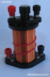
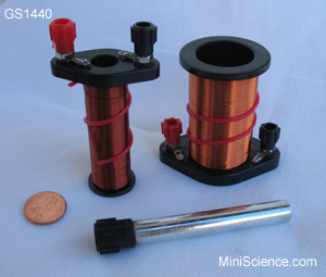
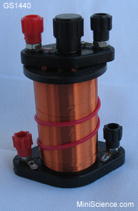
Educational transformers (Primary
Secondary Coil Set)
| Experimental Transformer for studying electromagnetic
induction, ferromagnetism and principles of a transformer. Consists of
two coils wound with enameled copper wire over heavy plastic spools
fitting one within the other. Both coils are equipped with binding posts
and a soft iron core for induction studies.
Product Code: GS1440 |
|
Used to study electromagnetic
induction & transformer principles. Overall height is at least 82
mm.
| Experimental transformers may be made
in different sizes, but they all serve the same functions. All coils are wrapped with magnet wire
with insulated binding posts as connectors. Either coil may be used as
primary or secondary. Advanced users may modify the effective number of
windings on the outer coil by tapping in wire or adding to the windings.
Price and availability |
 |
* Ideal transformer is a transformer that
does not loose any power in the form of heat.
|
Distributors of scientific and educational products
Where to buy?
Most pictures are linked to
the pricing and online store for fast and convenient ordering
Our products are available at the following
online stores. For large orders please call in advance and verify the
availability, wholesale discounts and shipping options. If you cannot find any
product in the online store of your choice, please use the search option of the
store or call (973)777-3113 for further assistance.
All orders will be shipped from our
warehouse in United States (USA). We ship worldwide
to most countries including U.S., Canada, Australia, United Kingdom, New
Zealand, Germany, France, Netherlands, and many other countries.
|
|